CLINK HERE FOR A COMPLETE INDEX TO ITEMS ON THIS BLOG

Thursday 21 April 2016

UNIVERSAL CARRIER 28mm

The twin Universal carriers are my next addition to the British Support List.
They come as plastic kits  from Warlord Games, are easy to assemble and come complete with 4 crew per vehicle.
I replaced the heads of the crew with ones from Warlord  British infantry to make them blend in better with the rest of my Brits.
I added:

  • Rifle rack with 2 Lee Endfields
  • back packs slung on the sides 
  • a chain on the front of one vehicles
  • bullet holes on the vehicle exterior
  • 2"/PIAT Mortar round container
  • Bren spare part pack

To give the vehicle flexibility in set up, I have enlisted the help of  tiny earth magnets to provide some modifications.
  • The ability to remove all the crew to represent them disembarked or represent crew casualties.
  • ability to remove both 2 AA Bren guns,PIAT and 2 inch mortar.


Same Carriers without crew,AA Brens,PIAT or 2 inch mortar.
Magnetized crew and weapons.
One of the crew supplied, with the kit has been replaced with a standing figure from my plastic Brit Infantry.His arms and body have been modified to fit the vehicle. 
He represents the Junior Leader.
Crew in position 
View of magnets:

  • inserted into the chassis of the vehicle 
  • inserted into the base of figures

This was achieved with the help of a hobby hand drill and super glued into position.

NOTE: 

  1. keep the polarity of the magnets the same for weapons on both vehicles.
  2. match the 4 crew of one vehicle with the same polarity while matching the other 4 crew from the other vehicle with a different polarity.
This will ensure that the correct crew will be able to be matched with their vehicle while allowing any weapon type to access any vehicle.
Carriers assembled,magnets sealed with Green stuff and Matt Black enamel undercoat applied.
Magnets where glued to the base of the weapons and reinforced with Green stuff.
Magic 

Showing placement of weapons.

Please note the AA Brens should be mounted on the left side. I modeled the rifle rack first and glued in place only to later realized I had insufficient space to  mount the AA Bren on the left.


Off to the gaming table.


Wednesday 13 April 2016

DIY STATIC GRASS APPLICATOR

I made this DIY Static grass applicator early last year, in preparation for future Terrain building projects, for the gaming table. 
Its also a cheap and ideal option for constructing  Tufts for Infantry bases.
On this page I describe: 

  1. How to make a DIY Static grass applicator.
  2. How to use the applicator to construct Tufts.  
  3. How to use it for general Terrain making. 

Completed static grass tufts for placement on miniature infantry bases
DIY Static grass applicator 

Disassembles to gain access to battery and flock holder


1. HOW TO MAKE A DIY STATIC GRASS APPLICATOR


Items needed
  • Small kitchen strainer
  • Small food container with lockable lid
  • IONB2 Negative ION Generator Module: maybe purchased for AUD $14.00 from Oatley Electronics at: http://oatleyelectronics.com/product_info.php?products_id=915
  • 9 volt connector
  • 9 volt battery
  • Plastic wire connector
  • Push button switch
  • led light
  • Crocodile clips
  • Extra wire
  • 2 x Plastic containers (or PVC drain pipe maybe substituted equal to the length of the 2 plastic containers approximately 8 inches in length, and use threaded end caps, found at your local hardware store)

  • Cut handles off strainer
  • Cut a circular hole in the top of the lid of the food container to fit mesh.
  • Push the strain thru the inside of the lid and glue into place.
  • Glue the lid of the circular container onto the base of the food container.
  • Drill 5 holes to allow for 3 x wire access, switch and led placement .
Electrical layout


2. HOW TO  USE THE  APPLICATOR TO CONSTRUCT TUFTS

Items needed to produce static grass

  • Static grass applicator
  • grass flock
  • your wife's oven baking paper 
  • metal biscuit lid
  • PVA glue
  • green paint
  • scissors
Open applicator lid and add flock and lock.
Cut wax paper sheet to fit metal lid
Clamp crocodile clip onto the rim of the metal container and mix 90:10 ratio of PVA to green paint
Use a instrument to apply varies size dots onto the waxed paper
Turn applicator on and shake the flock onto the dots.
Tufts of grass are formed as the applicator draws the grass upright over the PVA.
Remove excess
Completed tufts,continue this process until the sheet is completely covered and  allow to dry
Once dry, tufts are ready to remove off the baking paper as needed 
Currently working on completing  the basing of my British figures, hope to finish them soon.


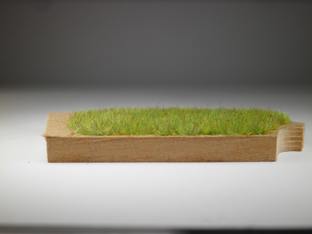
3.HOW TO  USE THE  APPLICATOR TO CONSTRUCT GRASS FIELD

Follow the same procedure as described in section 2 above with the difference, the crocodile clamp needs to be placed into the terrain board (weather its MDF or Styrene foam) via a pin or very thin nail to complete the electrical circuit. 
 Grass on MDF
side view 


Monday 4 April 2016

CHURCHILL TANK 28mm + SCRATCH BUILD AVRE TURRET


CHURCHILL TANK 28mm + SCRATCH BUILD AVRE TURRET 

Continuing to build up my late war British Support List, now with Armoured vehicles.
I have been busy assembling and painting vehicles while also working out a system for painting these vehicles.
While visiting  Andy's excellent COC AAR at: TINYHORDES
I decided I needed a Churchill AVRE. I pulled out my resin Warlords Churchill MK VII out of the box and decided I would have "a crack" at building a AVRE turret  from scratch (instead of forking out another 50 bucks to buy one,I also saw it as a bit of a challenge).
The  plan is to have 2 turrets, the normal Mk VII turret and the ARVE turret  that could be used interchangeable with the Mk VII chassis.
Here is the result !, happily named CYCLOPS.


HOW I CONSTRUCTED THE ARVE TURRET
1.Trace outline of turret on paper and cut out shape.
2.Clamp 2 pieces of 3mm MDF board together,trace the turret outline, using a saw cut out and superglue together.
3. Outline the slope on the front of the turret in pencil, chamfer using a wood file and sandpaper.
4.side view of trimmed slope  
5. Outline the step on the perimeter on top of the turret, using a modelling knife cut along the marked line
6. Continue cutting into the side of the turret and finally file down to create the step.
7.Make 2 cuts into both sides of turret.
8. Using sprues from left over model plastic kits, styrene pieces and brass rods, I was able to add the detail on the turret with the use of super glue to fix items in place. 


9. I fixed a sheet of styrene on the bottom of the turret to allow for clearance as the turret rotates. I used plastic conduit to link the turret to the chassis. Using a pencil mark the height that needs to be removed.
10. Using a hacksaw cut the conduit to size and check fit.
11. Check the clearance, remove turret and place glue on top lip of conduit, place it in the chassis then carefully place the turret onto the conduit, allow the glue to cure and remove.
12. To hold the turret in place and allow it to rotate I cut out a thin sheet of metal from a tin can and super glued inside the turret area on the chassis. I also used 3 mm x 1 mm earth magnets fixed onto the bottom of the turrets.  

What would I have done different?
To achieve a more smoother surface on the wooden turret, I would have encased it with thin styrene sheeting as I did with the large bin at the back of the turret. This would have also eliminated the need to cut out the step on-top of the turret and the grooves on the side.
Churchill AVRE


Churchill Mk VII